


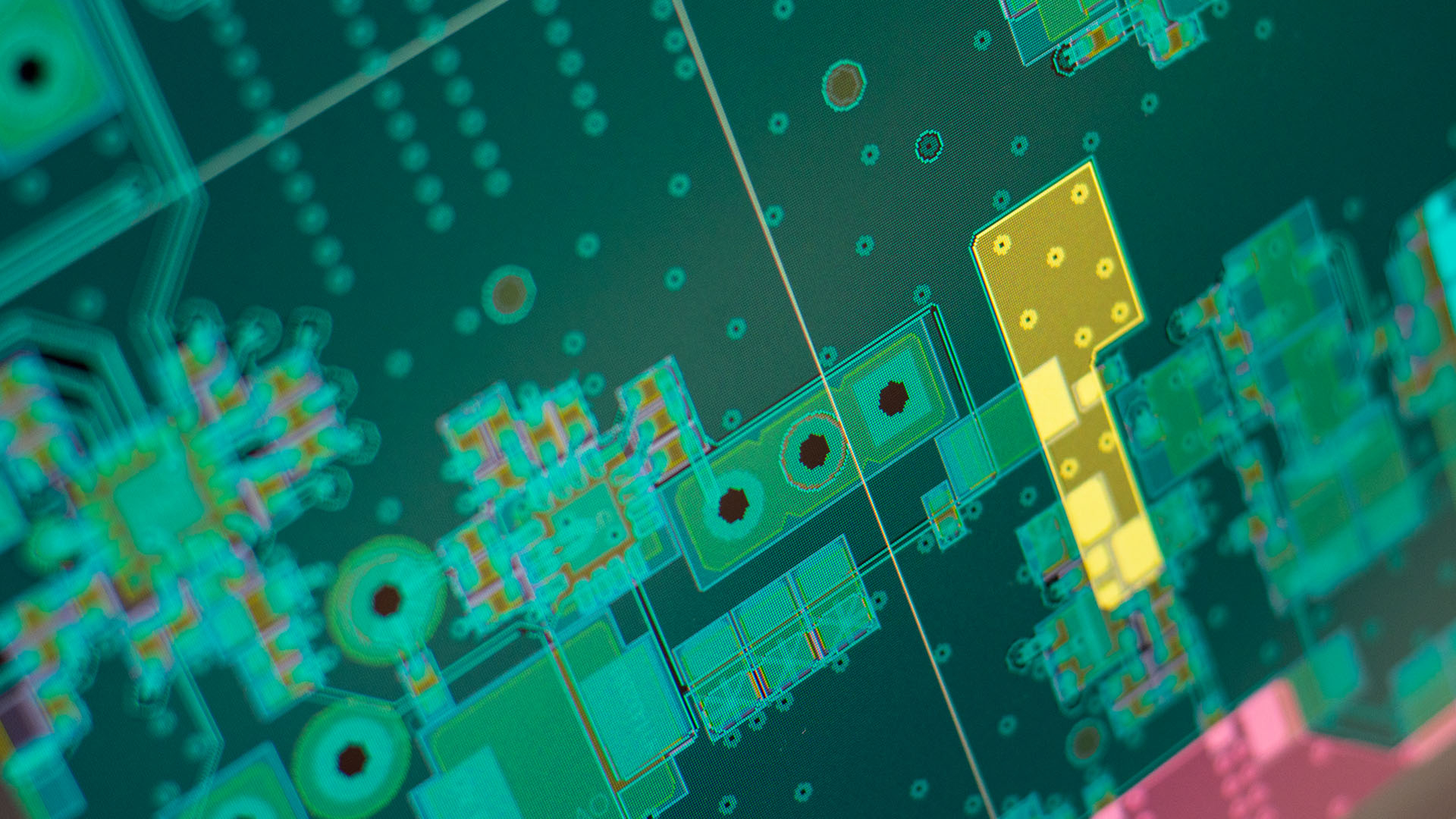
How to design electronic circuit - a step-by-step guide with expert tips

Designing electronic circuits involves a combination of creativity and accuracy. It's fairly obvious that if you want to be successful at electronic circuit design, you must understand each component and practice a lot. However, there are several guidelines that designers and DIY beginners must follow to create circuits that are both optimal and efficient.
In this step-by-step guide, we'll explore electronic design processes while combining knowledge and practical ideas. Meanwhile:
What does Electronic Circuit Design mean?
The electronic circuit design process involves the creation of electronic circuits, which can vary from individual transistors within an integrated circuit to more complex systems. While simple circuits can often be designed by a single individual, only some projects require the involvement of a dedicated circuit designer.
As a designer, understanding the intended functions of the circuit is important for its creation. Once the circuit is designed, thorough testing and verification are necessary to ensure it meets the desired specifications.
10 Easy Electronic Circuit Design Steps and Practices
Let's dive into the detailed steps of designing an electrical circuit:

1. Develop detailed specifications and build block diagram
Typically, start by preparing a thorough requirements specification. Cover all the bases, including input and output signals, voltage/current/power needs, operating temperature, frequency ranges, radiation shielding, board size, and component spacing. Throughout this process, keep a watchful eye on your available and estimated budget for the entire process.
Moving forward, build the block diagrams which stand as a primary guide, offering a clear reflection of the circuit's architecture and providing an overview of the schematic diagram. Consider them as your design's blueprint, offering a quick reference for future analyses.
Block diagrams become essential tools as your project unfolds. They allow you to adopt a systematic divide-and-conquer approach. By breaking down the diagram into distinct functional sections, you can implement and test each part independently. Understanding the functionality of each part of the block diagram is crucial, and some may even include signal conditioning circuits to ensure the data acquisition system can interpret the output effectively.
In practical terms, consider an example: a light-dependent resistor (LDR) sensor's output might need transformation into a voltage range readable by the microcontroller ADC. These circuit blocks can be replicated in other designs with similar requirements, promoting efficiency through design reuse.
Another important aspect is to give your schematic diagram a title and include your name on the title block. This not only adds a professional touch but also makes it easier for others to identify the creator. The schematic contains crucial details for constructing the circuit layout on the PCB or breadboard, serving as a comprehensive guide for future work.
2. Place Bypass, Coupling, and Decoupling Capacitors
To address the challenges of fluctuating output voltages and potential disruptions, circuit designers turn to coupling and decoupling capacitors. An effective circuit design technique is to select appropriate capacitors based on your application and guarantee their correct placement.
A Decoupling capacitor, strategically connected in parallel to the power source, plays a role in filtering incoming AC signals from the DC supply. By initiating the charging process from the power source and maintaining a stable charge level at Vcc, these capacitors act as guardians against voltage drop, ensuring a consistent and pure DC supply. They become essential in preventing any potential infraction or failure brought on by variations in the power supply.
On the other hand, coupling capacitors are vital parts of amplifier circuits because they allow low-frequency noise in output signals as well as DC elements to flow smoothly. These capacitors provide for a smooth operation when positioned strategically, especially in RF and audio applications where undesired noise can taint signal integrity.
Bypass capacitors are essential components in amplifier circuits and loudspeaker circuits because they function in parallel with the output signal. They serve to preserve the integrity of the pure DC signal by rerouting low-frequency noise to the ground. For situations where audio quality is critical, this careful balancing effort guarantees that the circuit receives a clean and noise-free signal.
3. Integrate Pull-up and Pull-down resistors
When dealing with digital circuits and microcontrollers, every designer should consider using pull-up and pull-down resistors. This essential idea allows us to skip and deal with the occurrence of the floating condition.
Digital integrated circuits (ICs) rely on specific logic levels, determined by input voltages that signal whether a binary value is interpreted as 1 or 0. The relationship between input and output voltage is crucial. However, when the input voltage falls within an indeterminate range, the IC may misinterpret the signal, leading to erratic behavior.
The solution? Tiny resistors are called pull-up and pull-down resistors.
- Pull-up resistors: Connect the input voltage to the power supply (e.g., 5V), nudging the voltage towards a clear Logic High.
- Pull-down resistors: Connect the input to ground (eg 0V), ensuring a clear Logic Low.
This prevents the "floating state" and makes sure the chip always knows what's going on.
Many modern microcontrollers have built-in pull-up/down resistors that can be turned on or off with code. This gives designers more flexibility, but they still need to check the microcontroller's specs to see what's available and decide if external resistors are needed.
In short: Pull-up/down resistors keep digital chips stable by ensuring their inputs are always at clear Logic High or Low levels.
4. Use Microcontroller-based circuit connections to enhance performance and efficiency
Microcontrollers bring a lot of benefits to circuit design, especially when it comes to making things simpler and smaller. They save time and reduce the size of the layout by replacing various components involved in analog-to-digital conversion. These microcontrollers come with handy features like timers, pulse-width modulators, analog-to-digital converters, digital-to-analog converters, and communication interfaces.
Modern microcontrollers, coming from different brands, offer advanced features like A/D conversion, communication abilities (Serial/SPI/I2C), timers, and more – all packed into these small, cost-effective chips. This not only boosts the performance of your circuit but also makes it more efficient while taking up less space.
5. Reduce power consumption using PWM signals
Creating energy-efficient circuits is required for devices that cannot replace or recharge their battery cells. To achieve this, designers often opt for Pulse Width Modulation (PWM), employing reliable components like microcontrollers or timer ICs. This approach enhances the energy efficiency of applications, particularly useful for motor and LED circuits.
PWM is a modulation technique that adjusts the pulse width of a signal based on the duty cycle. For instance, a PWM signal with a 75% duty cycle remains ON for 75% of the total period and OFF for 25%, effectively reducing the mean output power consumption. This modulation technique, facilitated by trustworthy microcontrollers or timer ICs, proves valuable in conserving energy in circuits powered by batteries.
Whether regulating LEDs or operating motors, PWM helps decrease energy use. The waveforms it generates are used in power converter topologies, which help to create an extremely efficient, lightweight, and cost-effective switched-mode power supply. In summary, implementing PWM signals into circuit design emerges as a fundamental method for optimizing energy consumption, particularly in battery-powered products.
6. Establish Effective Signal Return Paths and Ground for EMI Prevention
To prevent electromagnetic interference (EMI), circuit design must include strategic signal return channels and grounding. Each signal reference should have its trace that connects to a common ground. Rather than joining various chips' ground pins and attaching them to a single ground, connecting them individually to the same node reduces humming noise.
For mixed-signal boards, the most economical grounding technique is using a single ground plane with no splits. Maintaining return pathways as short as possible is critical for best performance.
7. Protect Against ESD, Reverse Polarity, Transients, and Over-Voltages
Protecting circuits from electrostatic discharge (ESD), reverse polarity, transients, and over-voltages is crucial for potent performance, especially in harsh environments. Utilizing components like metal-oxide varistors, transient voltage suppressor (TVS) diode arrays, clamping diodes, and gas discharge tubes (GDTs) helps effectively combat ESD. Introducing a small resistance between diodes and ICs dissipates voltage overflows, particularly in sensitive areas like communication interfaces and user inputs.
For reverse polarity protection, diodes or FET circuits can be used, with diodes being more suitable for low-power applications. Over-voltage protection is achieved through voltage limiters, electronic fuse chips, and thermistors. Modern ICs often include built-in protection circuits, and options like varistors, TVS diodes, and diode circuits provide effective voltage limiting.
Protection diodes are essential when driving relays with semiconductors to prevent voltage spikes during sudden power shutdowns. High-voltage capacitors need proper discharge paths, and understanding class X/class Y safety capacitors is crucial. These capacitors, placed strategically in the circuit, filter AC signals, reduce EMI, and mitigate the impact of voltage transients.
8. Choose the right components for the circuit design
Selecting components for electronic circuit design requires careful consideration of design requirements and sufficient margins for reliable operation. Various package options, including through-hole, surface mount, panel mount, and chassis mount, offer flexibility to meet different needs.
Here are some key tips for component selection:
- Thoroughly review component datasheets and integrate them into the design based on specified reference circuits or calculations.
- Choose parts that are unlikely to become obsolete and will remain available for at least 5-7 years.
- Derate parts to avoid operating them near their limits, which could lead to premature failure.
- Select components with ratings 1.5 - 2 times higher than the actual requirements to ensure reliability. For instance, ensure that resistors dissipate only 50% of their rated wattage.
- Maintain a spreadsheet with power dissipation calculations for each part, including values, types, and packages, to create a comprehensive bill of materials.
- Use standard component values whenever possible to reduce circuit costs and avoid parts with long lead times.
9. Select the most ideal EDA tool for the design
Simple schematic designs can be hand-drawn by anyone, even without professional expertise. However, for more complex circuit designs, the use of electronic computer-aided design (ECAD) software is necessary. The choice of ECAD software is often specified by the client or determined by the company. It is recommended to opt for professional CAD tools from reputable developers as they can generate schematic and layout designs, 3D views, artwork, bill of materials, and Gerber files for the final production of the product.
Various Electronic Design Automation (EDA) firms and developers offer both free and paid ECAD tools, such as KiCAD for free and Altium Designer, OrCAD, etc., for paid options. The selection of software depends on the designer's preferences and the requirements of the circuit design process. Ultimately, it is necessary to master the chosen ECAD tool.
10. Carry out Testing and Simulation tests
Conduct simulations and functional assessments to validate and test crucial circuit blocks in the design. Simulation software, offered by various Electronic Design Automation (EDA) tools, allows for analyzing the correct functionality of individual blocks within the circuit. In instances where the circuit does not perform as required, adjustments can be made accordingly.
It's important to note that simulation software has limitations, and accurate results may not always be guaranteed. Therefore, it is advisable to physically assemble the circuit section on a breadboard to test its functionality. In the event of errors in any circuit block, troubleshooting and rectification can be carried out in subsequent design iterations.

Where can I design an electronic circuit?
When seeking a platform to design electronic circuits, consider partnering with VECTOR BLUE HUB. With our comprehensive suite of tools and resources, including electronic computer-aided design (ECAD) software, simulation capabilities, and access to expert guidance, you can efficiently and effectively design electronic circuits tailored to your specific needs.
By collaborating with VECTOR BLUE HUB, you gain access to a trusted partner dedicated to facilitating your circuit design journey and helping you achieve your objectives with confidence and precision.

Wojciech Jesionkowski
Wojciech leads the development team and strives to bring customers’ ideas to life. During his 14 years at VECTOR as an engineer, he has gained strong problem-solving skills and analytical thinking in product development. Privately, he's a father who loves to spend time with his family on shared outdoor activities and travels.