Types of PCB Connectors: Find the right solution for your needs!
Printed Circuit Board (PCB) connectors are important components in electronic devices such as sensors, microcontrollers, and peripherals, to the PCB, enabling the transmission of electrical signals and power between different components. They come in a wide variety of types, each designed for specific applications and performance requirements. A broad range of PCB connection types are available to meet various applications, conditions, circuit types, and design needs.
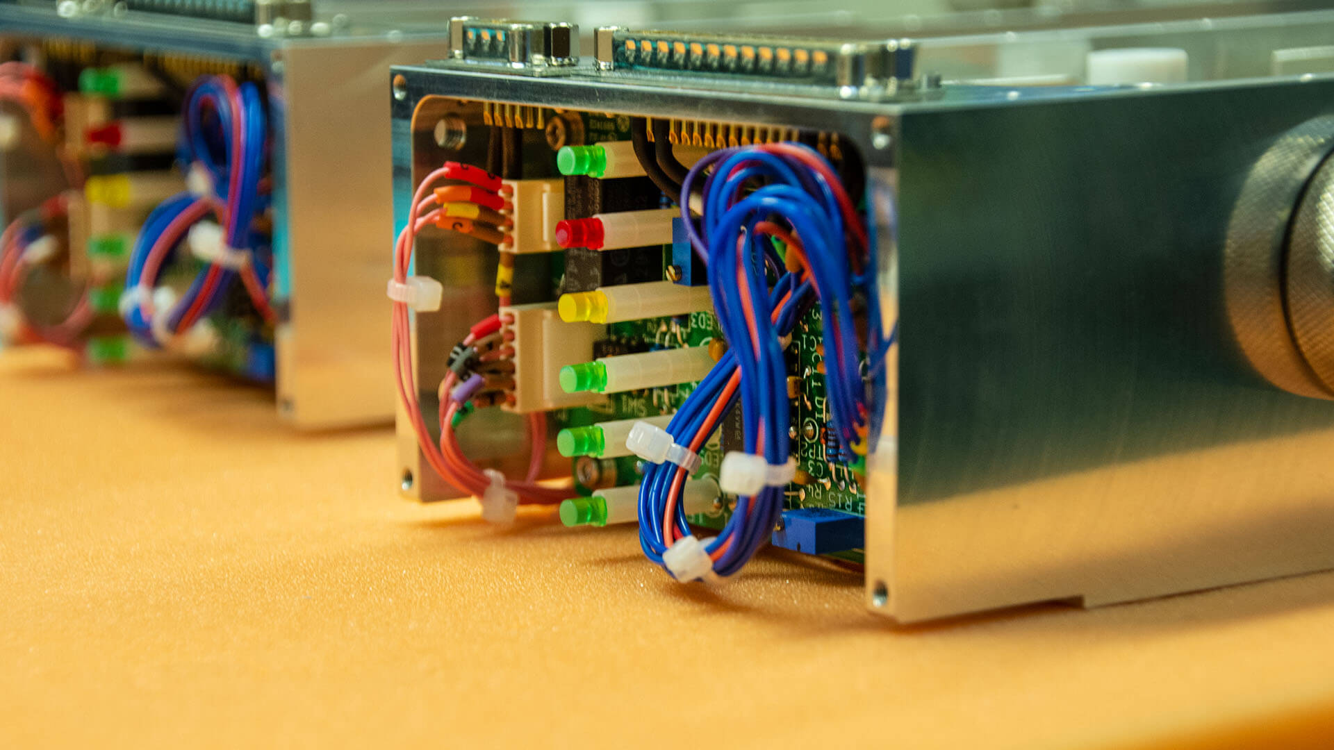
Understanding the basics of PCB connector selection allows you to pick the best solutions for your electronics projects and products. In this blog post, we will explore the different types of PCB board connectors, PCB mount types, their characteristics, and their typical applications. We will also provide a brief overview of the mounting and connection methods commonly used for PCB connectors.
What is a PCB Connector?
PCB connectors, often known as sockets or terminals, are essential components of electrical systems. These components include a wide range of elements, from integrated circuits and sensors to switches and power supply. Various electronic components are placed on conductive pathways or connected between designated areas on a printed circuit board (PCB). In some instances, additional components or equipment may be necessary to create connections within the board or between different boards.
PCB connectors are used to transfer power or signals from a single point to another. The transfer might occur within the PCB or between PCBs. PCB connections are installed on the PCB regardless of the applications. Instead of permanently connecting components and boards using direct wiring, PCB connectors are utilized to provide detachable and flexible connections during the assembly stage.
In addition to connecting wires within a single electronic system, connectors considerably reduce the need for traditional soldering techniques, soldering irons, and insulating tape, ultimately enhancing overall connection efficiency. Connectors are meticulously engineered to maximize signal transmission, employing conductive materials like copper and corrosion-resistant elements to enhance durability. They typically incorporate current-carrying components, such as terminal strips or metal strips, tightly secured within an insulating housing. This adaptable design simplifies electronic system assembly and maintenance, while also expediting modular installation or removal on PCBs.
Selecting the right connector types
PCB connectors are used to connect different components of a PCB together, as well as to connect one PCB or other PCB and to cables and wires. The type of PCB connector used depends on the specific needs of the application, such as the size, weight, power requirements, and operating environment of the PCB.
Selecting the appropriate PCB connector is critical for the overall operation and integrity of electronic devices. Several factors highlight the significance of this:
Compatibility: Different connectors have distinct pin configurations, sizes, and shapes. Employing an incompatible connector can hinder or prevent components from effectively connecting to the PCB.
Cost: Connectors vary in price. Utilizing a connector that is not essential for the specific application can add unnecessary expense to the device.
Reliability: Connectors vary in their ability to withstand harsh environments. Some are designed to endure high temperatures, vibrations, or moisture, while others may not be suitable for such conditions. Choosing a connector that is not designed for the specific application can increase the risk of failure.
Safety: Some connectors incorporate safety features such as locking mechanisms or polarization, preventing incorrect insertion or accidental disconnection. Neglecting these safety features can pose a risk to the user or the device, or hinder the creation of a reliable connection.
Performance: Connectors differ in their signal transmission speeds and capacities. Using an unsuitable connector can result in signal degradation, leading to slower data transfer rates or even data loss.
What are the different types of PCB connectors?
In the most basic sense, there are three categories of PCB connector types based on how they are connected.
Board-to-board connectors:
Board-to-board connectors allow us to connect PCBs without cables. They can be used to create permanent or reversible signal connections between two PCBs. Board-to-board connectors are ideal for connecting PCBs in limited space, and they can be used to connect PCBs in either a parallel or perpendicular direction. Mezzanine connectors and backplane connectors are two types of BTB connectors that are often used in stacked PCB applications and communication and computer systems, respectively.
Wire-to-wire connectors:
When prototyping electrical devices, we often use cables and wires in addition to PCBs. In some cases, we need to connect cables to each other. One end of the cable is permanently attached to a wire, while the other end is detachable. The permanent connection can be made using crimping or insulation displacement contact.
Wire to board connector:
Wire-to-board connector allows for easy connections between wires and printed circuit boards. It is a device that makes it easier to connect circuits together. The wire end of the connector is the same as the cable-to-cable connector, but the board end can be either a press-fit connector or a two-piece connector that is soldered together.
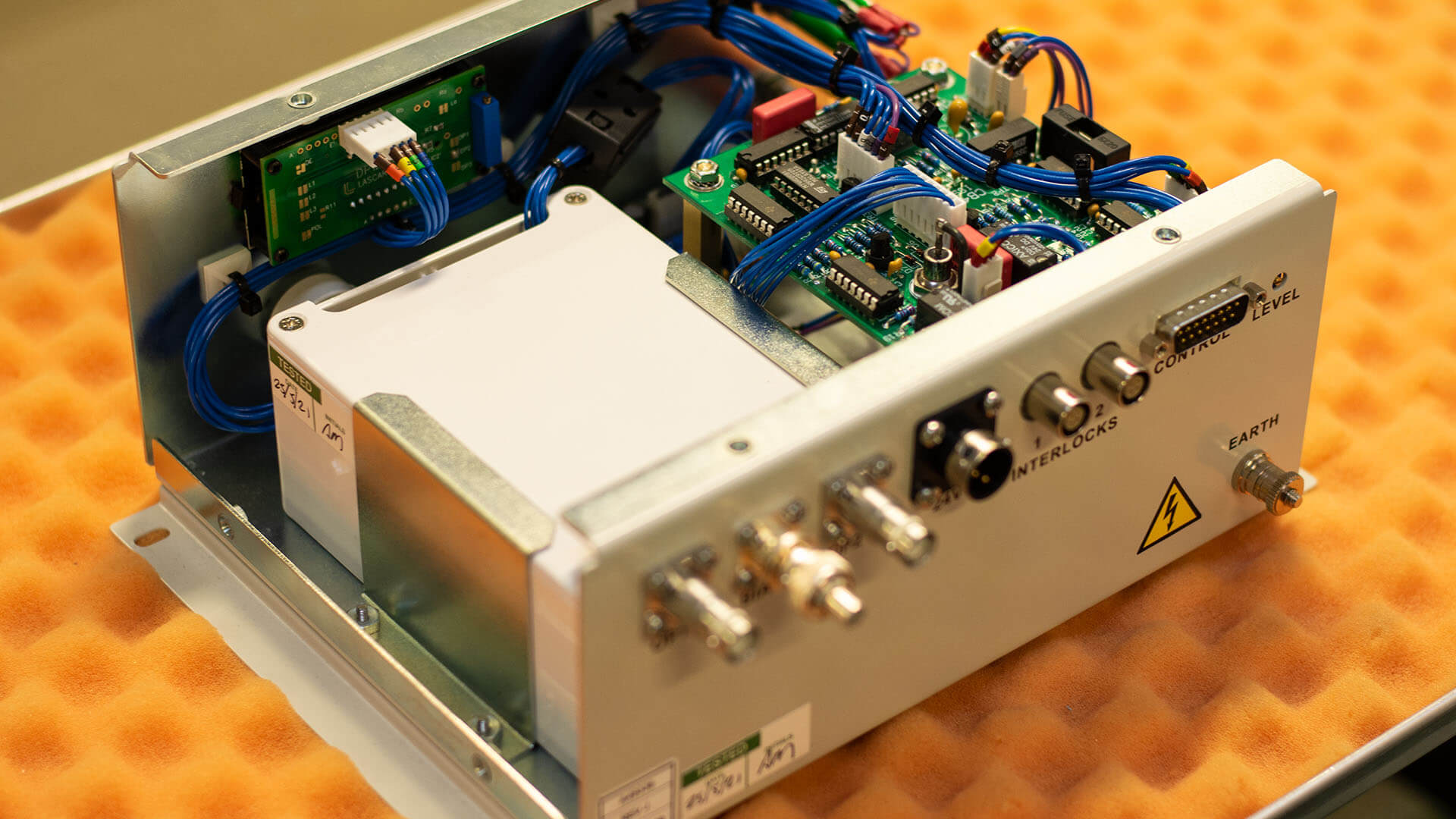
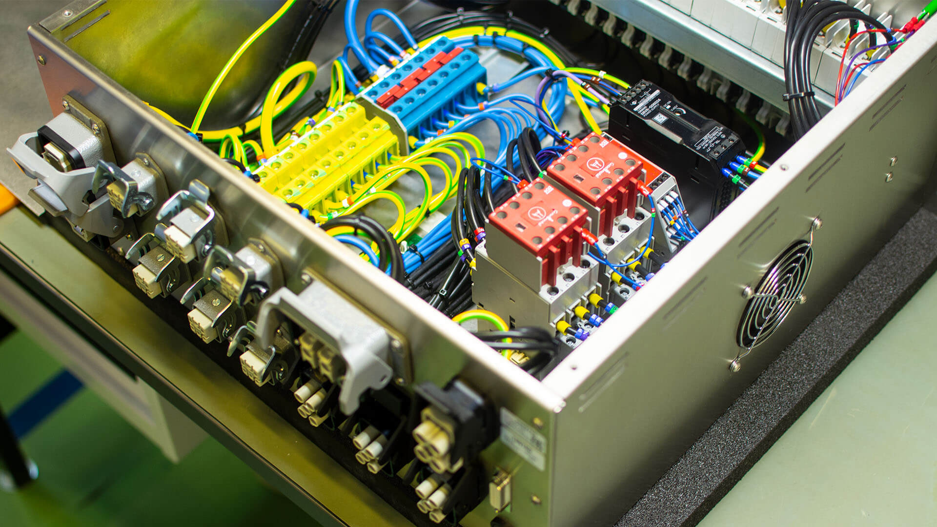
PCB connector Types based on Application
PCB board connectors are used in a wide variety of electronic devices, each with its own unique type, size, and function. As a result, there are many different types of PCB connectors available to choose from.
Pin Headers and Sockets
A Pin header/Socket is a versatile connector that can be used for both board-to-board and wire-to-board connections. They come in a variety of configurations, including surface mount, right-angle, and straight. They also offer a wide range of pin spacings and pin counts. They are one of the most common types of PCB connectors. They consist of a row of pins on one connector that fit into corresponding holes on the other connector. They are used for a variety of applications, such as connecting a PCB to a display, a keyboard, or other peripherals. They are also known as Male PCB connectors (Pin header) and Female PCB connectors (Socket or header receptacle). The sockets are designed to fit snugly around male connectors, creating a pathway for signals (power or data) to pass through. Pin headers and wire housings (female) are arranged in rows.
Backplane connector
They are a type of PCB connector that connects two PCBs that are close together (board-to-board connectors). They are support structures that allow other PCBs or external devices to be connected to them. They also provide an interface for integrating other system components, such as daughterboards. Mezzanine connectors can be used to connect daughterboards to backplanes in a vertical or parallel configuration. High-density mezzanine connectors are often used in applications such as communication, industrial equipment, and data processing.
USB connectors
USB connectors are the most widely used PCB connectors today. This is not surprising, as they are used in a wide variety of devices, such as tablets, keyboards, smartphones, digital cameras, computer mice, and more. All USB PCB connectors have at least four contact points: one for power, one for ground, and two for data transmission and reception. There are different types of usb connector including Type A, Type B, and Type C. Type C USB connector is becoming more popular because they can be plugged in either way, which makes them easier to use.
USB-A: The most common USB type, found on computers and laptops.
USB-B: A larger and more durable USB type, found on older devices and printers.
USB-Micro: A smaller USB type, found on smartphones, external hard drives, and tablets.
USB-C: The newest and most versatile USB type, found on modern laptops, smartphones, and other devices.
Power Connectors Power connectors are used to connect power sources and other high-power devices to a PCB. Power supply connectors are simply interfaces that connect power sources to devices. They come in a variety of shapes and sizes, such as barrel connectors, blade connectors, and screw terminals. They are designed to carry large amounts of current and voltage, and they are typically rated for a specific range of amperage and voltage.
Connector for the automotive industry
Automotive connectors must meet the USCAR-20 standard, which sets performance requirements for electrical connector systems in cars. This standard requires that the contact surfaces of electrical connectors remain reliable throughout the entire service life of the connector. Automotive connectors can be classified by their installation position (body system, chassis system, instrument panel, engine, or safety system) or by their electrical properties (ECU, temperature sensing, central electric system, air conditioning, recreation, etc.).
D-Sub Connectors
D-sub connectors, which are also known as D-shell connectors, are a type of electrical interface connector that is named after its D-shaped housing. These connectors are commonly used to connect video, audio, and serial data devices. D-sub connectors come in a variety of sizes and have different numbers of pins, but the most common types are the DB-9, DB-15, and DB-25 connectors. Although they are quite old, this interface is still pretty much in use.
Terminal block
A terminal block is a female socket that makes it easy to connect wires. A terminal block can also be called a wire connector. Terminal blocks are classified into many types, including plug-in, fence, track, spring, and through-wall.
Fiber optic connectors
Optical fiber pcb connectors are devices that allow for the detachable and flexible connection of optical fibers. They precisely align the two end faces of the fibers to maximize the coupling of optical energy from the transmitting fiber to the receiving fiber, and minimize the impact of the connector on the optical link performance. Optical fiber connectors can be classified by their physical structure into FC, SC, ST, LC, D4, DIN, MU, and MT connectors.
Circular connectors
Circular pcb connectors, also known as aviation plugs, are widely used in aerospace applications because they can handle large currents and provide good protection from electromagnetic interference (EMI).
Memory Connectors
The word refers to a connection interface for memory devices, which can be categorized depending on their specific applications.
Modular/Ethernet connectors
These connectors, also known as Ethernet, were used to connect network devices. RJ-45 interface, RJ-11 interface, SC fiber interface, FDDI interface, AUI interface, BNC interface, and Console interface are the most prevalent Ethernet interface types.
Wrap Up
When choosing a PCB connector, there are several factors to consider, such as the type of connector, the number of pins, the current rating, the voltage rating, and the mating cycles. You should also consider the environment in which your PCB will be used in a harsh environment, you will need to choose a connector that is ideal for that environment.
VECTOR BLUE HUB is a PCB manufacturing service company that stands out from the competition with our high-quality PCBs, fast turnaround times, competitive prices, and excellent customer service.


Jarosław Krzyżanowski
Jarosław has over fifteen years of experience in electronics manufacturing processes (SMT, THT, AOI, X-RAY, SOLDER WAVE, SELECTIVE, ASSEMBLY). As Process Leader, he ensures an appropriate level of skill in the manufacturing staff, work standards, processes, the appropriate workplace infrastructure, tools and the best use of technological solutions. He gets the most satisfaction out of teamwork. He also likes to look for out-of-the-box innovative solutions our customers require. Music is Jarek’s greatest passion; he also loves family walks and DIY.